
PRODUCT RANGE
Rated Output : 50 kVAR to 4000 kVAR
Detuning factor : 0.2% to 14 %
Rated Voltage : 380 Volt, 400 Volt, 440 Volt, 480 Volt, 525 Volt, 690 Volt, and 1000 Volt
Type of reactor : Dry type Aluminum wound / copper wound.
Type of Capacitor : Double dialectic ultra-heavy duty All PP Capacitors.
SHARDA offers perfect solution to minimize Harmonics level of industries where non-linear load like VFD, Electronics load, Convertors, Voltage booster equipment’s are present.
First, our technical executive analyse full system and as per system requirements to reduce voltage and current harmonics level compliances to IEEE STD 519. We provide tuned or detuned filter.
SHARDA manufactures capacitor and reactor which is used in Harmonics filter has sturdy design with considering all electrical and mechanical parameters to achieve harmonics level to IEEE standard level in system.
Current carrying capacity of reactor is 300% to the rated current. The temperature of the reactor increase at time of full working is only 10% to 20% beyond the ambient temperature.
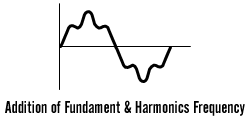
Harmonics are integral multiple of some fundamental frequency that, when added together result is distorted waveform as shown below,
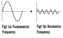
Above figs. shows the graph of fundamental as well as harmonics frequency, respectively and the below fig. shows how it looks when harmonics enters in to the system.
Symptoms of Harmonics when it present in System :
Causes of Harmonics :
Harmonics are generated by various sources which inherently have non-linear load like VFD, Diode, Computer, & all electronics equipment’s. That is generally where frequency as well as voltage conversion system are used. These loads use current in a pulsating manner at times of feed harmonic currents back in to the wiring. In non-linear load current waveform is different from voltage waveform.
Standard Harmonic Limit as per IEEE :
The Institute of Electrical & Electronics Engineering (IEEE) has set recommended limit on both current & voltage distortion in IEEE 519-1992
| Sr. No. | Bus Voltage at PCC | Individual Voltage Distortion | Total Voltage Distortion |
| 1 | Below 69 kV | 3.0 | 5.0 |
| 2 | 69 kV to 161 kV | 1.5 | 2.5 |
| 3 | 161 kV & above | 1.0 | 1.5 |
IEEE STD 519-1992 Harmonics Voltage Distortion Limit
IEEE STD 519-1992 Harmonics Current Distortion Limit for general distribution system
Maximum Harmonics Current Distortion (IL) :
The Institute of Electrical & Electronics Engineering (IEEE) has set recommended limit on both current & voltage distortion in IEEE 519-1992
| Sr No. | Isc/I}} | <11 | 11≤h<17 | 17≤h<23 | 23≤h<25 | 35≤h | TDD |
| 1 | <20 | 4 | 2 | 1.5 | 0.6 | 0.3 | 5 |
| 2 | 20-50 | 7 | 3.5 | 2.5 | 1 | 0.5 | 8 |
| 3 | 50-100 | 10 | 4.5 | 4 | 1.5 | 0.7 | 12 |
| 4 | 100-1000 | 12 | 5.5 | 5 | 2 | 1 | 15 |
| 5 | >1000 | 15 | 7.0 | 6 | 2.5 | 1.4 | 20 |
Even harmonics are limited to 25% of odd harmonics limits above.
Current distortion that result in a DC offset, for example, half wave converter are not allowed.
Where,
Isc: Maximum short-circuit current at the Point of Common Coupling (PCC).
IL: Maximum demand load current (Fundamental) at the PCC.
TDD: Total Demand Distortion


Technical Data Sheet :
| Sr. No. | Description | Technical data |
| 1 | Make | SHARDA Electronics & Co. Plot No. J-32 MIDC Kupwad Sangli, 416436, Maharashtra, India. Make : SHARDA |
| 2 | IS Reference | IS 5553 : 1989 |
| 3 | Type of winding | Copper / Aluminum |
| 4 | Rated Banking Output | 50 kVAR to 4000 kVAR |
| 5 | Rated Voltage | 380 volt to 1000 volt |
| 6 | Frequency | 50 / 60 Hz |
| 7 | Detuning Factor | 0.2%, 0.4%, 2%, 5.67%, 7%, 14% |
| 8 | Linearity | 200 % |
| 9 | Ambient Temperature | 50°C |
| 10 | Insulation Class | F class |
| 11 | Cooling Method | Natural Cooling (AN) |
| 12 | Temperature Sensor | Normally Closed at 140 °C |
| 13 | Installation | Indoor, LT panel Mounted |
| 14 | Altitude | 1000 meter above sea level |
| 15 | Max Cont. Current | 135% for continues |